This guide explains how to quickly start the MicroPlayer mkIII for first use.
TABLE OF CONTENTS
- 1. Presentation
- 2. Preparing the Storage Media
- 3. Connecting Input Contacts
- 4. Connecting Output Contacts
- 5. First Startup
- 6. Firmware Update
- 7. Reference
1. Presentation
The MicroPlayer mkIII is a standalone audio player supporting WAV and MP3 files stored on an SD card or USB drive. Files can be played automatically at power-up or triggered by external events (input contacts, RS-232 commands, infrared remote control).

1. Volume knob for the amplified speaker output | 8. USB 2.0 host connector for USB drive, Type-A |
2. Configurable button A (decreases volume by default) | 9. RS-232 serial connection and power output, detachable terminal block |
3. Configurable button B (increases volume by default) | 10. 4 optocoupled input contacts and power output, detachable terminal block |
4. SD card slot | 11. 2 MOSFET outputs and power output, detachable terminal block |
5. Status LED | 12. Stereo audio output at line level 0 dBu, RCA connectors |
6. Infrared sensor | 13. Stereo amplified speaker audio output, Class D, detachable terminal blocks |
7. External DC power connector | 14. Stereo headphone audio output, standard 3.5 mm jack connector (TRS) |
2. Preparing the Storage Media
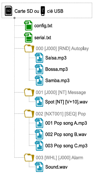
Select a high-quality SD card or USB drive and format it as FAT32. Store the necessary files according to the organization required by the player (see the example below). Do not use special characters or accented letters.
- Files at the root of the storage media:
- config.txt (optional): Player configuration file. See the Configuration File section.
- serial.txt (optional): File defining the serial frames to send. See the RS-232 Serial Connection section.
- Folder organization at the root:
- No subfolders allowed.
- Naming: xxx[TAG1][TAG2]Name
- xxx: Folder number from 000 to 999 used by commands. The AutoPlay function uses folder 000.
- [TAGx] (optional): Tags controlling playback. See the Folder and File Tags section.
- Name (optional): Folder name (free).
- Organization of audio files in folders:
- Format: WAV or MP3
- Naming: xxx[TAG1][TAG2]Name.ext
- xxx: File number from 001 to 999 defining the playback order in sequential mode. Optional and unused in random mode.
- [TAGx] (optional): Tags controlling playback.
- Name (optional): File name (free).
- ext: wav or mp3 extension.
3. Connecting Input Contacts
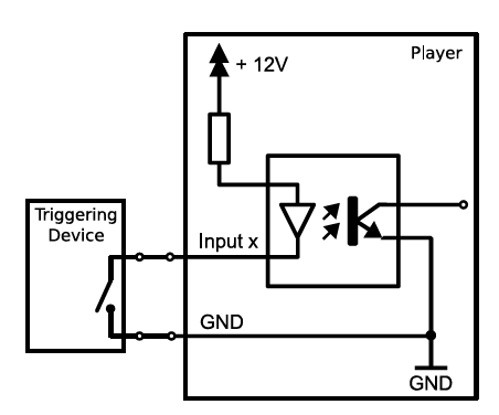
The player’s 4 input contacts are used to generate events. Trigger systems can be connected to them (e.g., push button, presence detector, relay, programmable controller, SensoPad, IRPad, etc.). They must behave like open or closed contacts between an input and the player’s ground, with activation occurring on a closed contact.
The activation states (0 for open or 1 for closed) of the input contacts are combined to form a binary code identifying the generated event:
Combination xxx = Input1 + Input2 × 2 + Input3 × 4 + Input4 × 8
A command is assigned to each event.
By default, the INPUTxxx event resulting from the combination value xxx of the inputs is associated with starting the playback of folder xxx.
The config.txt file allows you to modify the commands assigned to the first 15 combinations.
Up to 4 combinations (001, 002, 004, 008), trigger systems can be directly connected to the inputs. Beyond this, a diode-based circuit can be used to achieve up to 15 combinations (e.g., with the Ext15In card).
Example circuit: 15 push buttons to 4 inputs
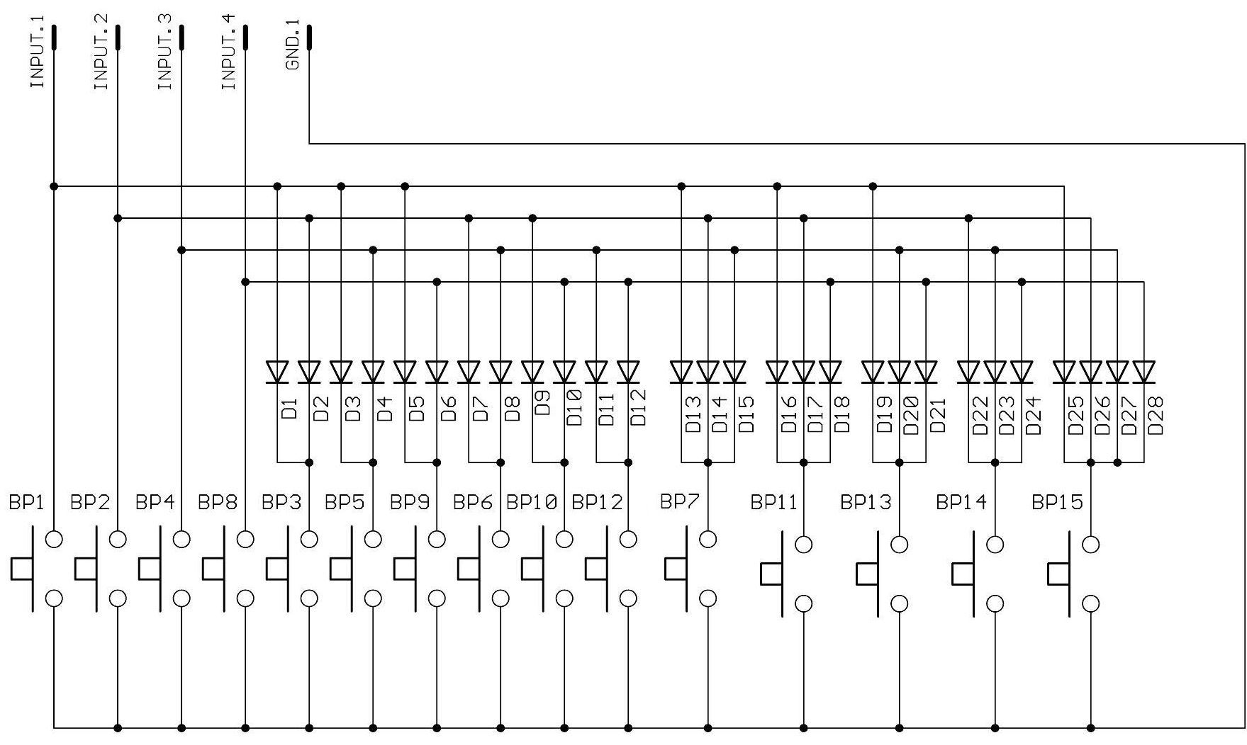
| Button | Event |
| BP1 | INPUT001 |
| BP2 | INPUT002 |
| BP3 | INPUT003 |
| BP4 | INPUT004 |
| BP5 | INPUT005 |
| BP6 | INPUT006 |
| BP7 | INPUT007 |
| BP8 | INPUT008 |
| BP9 | INPUT009 |
| BP10 | INPUT010 |
| BP11 | INPUT011 |
| BP12 | INPUT012 |
| BP13 | INPUT013 |
| BP14 | INPUT014 |
| BP15 | INPUT015 |
4. Connecting Output Contacts
The MicroPlayer mkIII offers 2 outputs with MOSFET switches (up to 500 mA per output) to control power relays, motor controllers, lights, players, and various devices. The states of the 2 output contacts can be controlled using the folder and file tag [RLxy]. x and y represent the activation states of outputs 1 and 2:
| Activation State | Description |
| 0 | Output contact opens at the start of playback. |
| 1 | Output contact closes at the start of playback and opens at the end. |
| 2 | Output contact closes at the start of playback. |
Examples:
- 001[RL00]: Both output contacts open when playback of folder 001 starts.
- 002[RL10]: Output contact 1 closes during playback of folder 002, and output contact 2 opens when playback of folder 002 starts.
- SongA[RL21].mp3: Output contact 1 closes when playback of the MP3 file starts, and output contact 2 closes during playback of the MP3 file.
5. First Startup
- Ensure the player is powered off (power adapter unplugged).
- Connect the audio outputs to the audio system as needed.
- Connect the input and output contacts as needed. See the Connecting Input Contacts and Connecting Output Contacts sections.
- Connect the RS-232 serial link if needed.
- Insert the prepared storage media. See the Preparing the Storage Media section.
- Power on the player by plugging in the power adapter.
- The player is operational.
6. Firmware Update
Start the player with a firmware file MPMK2.bin placed at the root of a FAT32-formatted SD card.
Firmware updates via USB drive are not supported.
7. Reference
7.1 Folder and File Tags
| Tag | Folder | File | Parameters | Description | ||
| Min. | Max. | Default | ||||
| [Jxxx] | ● | ● | 000 | 999 | Jump to folder xxx at the end of playback. | |
| [RET] | ● | Return to the previous folder at the end of playback. | ||||
| [RND] and [SEQ] | ● | [RND] | Random or sequential playback mode for the folder. | |||
| [V+xx] and [V-xx] | ● | ● | Relative volume of the folder or file. | |||
| [NT] | ● | ● | Lock all commands from input contacts, configurable front panel buttons, and folder change commands from the serial link. | |||
| [RLxy] | ● | ● | Definition of the state of all output contacts (x for output 1 and y for output 2): 0 = open, 1 = close during playback, 2 = close. | |||
| [RSxxx] | ● | Send RS-232 frame #xxx from the serial.txt file. | ||||
| [WHL] | ● | Play the folder as long as the corresponding input combination remains active. | ||||
| [NXTxxx] | ● | Play the next xxx files each time the folder is played. | ||||
7.2 Configuration File
The configuration file config.txt is a plain text file placed at the root of the storage media. Each line allows you to define a player parameter according to the table below.
| Parameter Definition | Accepted Values | Default Value | Description |
| #ID:xxx | 001 to 127 | 001 | Player identifier on the RS-232 serial link. |
| #VOLUME:xx | 00 to 64 | Last used value | Player volume at power-up. |
| #RS_MONITORING:x | 0: No monitoring 1: Daisy Chain mode 2: Monitoring 3: Extended monitoring | 0 | Monitoring mode for the RS-232 serial link. |
| #BOOT:xxx | 000 to 999 | 000 | Folder to play at power-up. |
| #INPUTxx:cmd | xx: 01 to 15 cmd: See the command table | FOLDER0xx | Commands assigned to input contact combinations. |
| #BUTTONx:cmd | x: 1 or 2 cmd: See the command table | BUTTON1:VOLUME_MINUS BUTTON2:VOLUME_PLUS | Commands assigned to the special buttons on the infrared remote control and the player’s front panel. |
| #BAUDRATE:xxxxx | 9600, 19200, 38400 | 19200 | Baud rate for the RS-232 serial port. |
| #POWER:x | 0: Normal mode 1: Power-saving mode | 0 | Activation of power-saving mode. |
| Command | Parameters | Description | |
| Min. | Max. | ||
| PLAY | Play the last played file. | ||
| STOP | Stop playback. | ||
| NEXT_TRACK, PREV_TRACK | Play the next/previous file in the current folder. | ||
| NEXT_FOLD, PREV_FOLD | Play the next/previous folder. | ||
| FOLDERxxx | 000 | 999 | Play folder xxx. |
| VOLUME_PLUS, VOLUME_MINUS | Increase/decrease volume by one step. | ||
| RSxxx | 001 | 999 | Send RS-232 frame #xxx from the serial.txt file. |
7.3 RS-232 Serial Connection
This link allows the player to receive commands, send arbitrary frames, and send status information.
By default, it is configured as follows (modifiable with config.txt):
| Baud Rate | Start Bit(s) | Data Bit(s) | Parity Bit(s) | Stop Bit(s) | Handshake |
| 19200 | 1 | 8 | 0 | 1 | None |
The reception protocol is based on a 3-byte frame: “Status”, “Command”, and “Data”:
| Status | Description | Command | Description | Data | Description |
| 80h | All players. | 01h, 11h, 21h, 31h, 41h, 51h, 61h, and 71h | Play a folder from a bank of 128 folders. command = bank × 10h + 1 | 00h to 7Fh | Folder number in the bank. |
| 81h to FFh | Only the player with identifier 001 to 127. | 02h | Playback and volume control. | 01h | Play the last played file. |
| 02h | Stop playback. | ||||
| 03h | Next file in the current folder. | ||||
| 04h | Previous file in the current folder. | ||||
| 06h | Play the next folder. | ||||
| 07h | Play the previous folder. | ||||
| 09h | Increase volume by one step. | ||||
| 0Ah | Decrease volume by one step. | ||||
| 03h | Volume control. | 00h to 40h | Volume value. |
Arbitrary frames can be sent using the [RSxxx] tag and input contacts. These frames must be defined in the serial.txt file at the root of the storage media, in the format #xxx:tt tt tt..., with one definition per line (e.g., #002:98 75 21 35 45 B2).
The monitoring protocol is structured like the reception protocol. The status byte has the same meaning. This protocol sends the following command and data bytes, depending on the mode selected in the config.txt file.
| Mode | Description | Command | Data | Description | |
| 0 | No monitoring | The player sends nothing other than the frames from the serial.txt file. | |||
| 1 | Daisy Chain | The player echoes everything it receives. | |||
| 2 | Monitoring | 00h | 00h | Player ready. Sent at power-up. | Sent on event. |
| 03h | Start of playback. | ||||
| 04h | End of playback. | ||||
| 3 | Extended monitoring | 00h | 00h | Player ready. Sent at power-up. | |
| 03h | Start of playback. | ||||
| 04h | End of playback. | ||||
| 01h | No playback. | Sent every 250 ms, unless the player is unavailable due to an issue. | |||
| 02h | Playback in progress. | ||||
Was this article helpful?
That’s Great!
Thank you for your feedback
Sorry! We couldn't be helpful
Thank you for your feedback
Feedback sent
We appreciate your effort and will try to fix the article