The SensoPad is designed to be connected to a power source and a control or triggering system. Its wiring is straightforward and relies on four distinct wires, each with a specific function. A clear understanding of these connections is essential to ensure optimal operation of the detector.
Wire Description
The SensoPad is equipped with four wires, each identified by a specific color:
- Red wire: Positive power supply (+V). Must be connected to the positive terminal of your power source (7V to 15V DC).
- Black wire: Negative power supply (0V). Must be connected to the ground (GND) of your power source.
- Yellow wire: Switching output (OUT). This wire transmits the detection signal. It can be connected to the trigger input of a compatible device (e.g., video player, control system).
- Blue wire: Negative power supply for the output (0V). Must be connected to the ground (GND) to complete the output circuit.
Connection Diagram
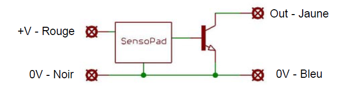
To connect the SensoPad:
- Connect the red wire to the positive terminal (+V) of your power supply (7V to 15V DC).
- Connect the black wire to the negative terminal (0V or GND) of your power supply.
- Connect the yellow wire to the trigger input of the device you want to control (e.g., trigger input of a VP320/VP330 player).
- Connect the blue wire to the ground (0V or GND) of your system to complete the output circuit.
Electrical Specifications
Ensure your power supply meets the following specifications to avoid damaging the SensoPad:
- Power supply voltage: 7V to 15V DC (12V nominal).
- Current consumption: Approximately 10 mA.
- Output: Open collector type, compatible with a maximum voltage of 50V and a current of 100 mA.
Note: The SensoPad is designed for low power consumption, making it ideal for applications requiring a stable and economical power supply.
Was this article helpful?
That’s Great!
Thank you for your feedback
Sorry! We couldn't be helpful
Thank you for your feedback
Feedback sent
We appreciate your effort and will try to fix the article