The MicroPlayer mkIII can communicate with other devices. It can receive commands via its Rx input or transmit information via its Tx output. The player complies with the RS-232 standard.
TABLE OF CONTENTS
Default value: 19200 Baud - 8 bits - No parity - 1 start bit - 1 stop bit
The baud rate can be modified via the config.txt file.
Reception Protocol
With the input protocol, the player can receive commands to start folder playback or adjust the volume. Additionally, when using multiple players on the same connection, the player responds to its own number (defined in the config.txt file, see chapter 5) or to a general command.
The reception protocol is built from a 3-byte frame.
Byte 1 (Status) + Byte 2 (Command) + Byte 3 (Data)

Reminder:
- a byte consists of 8 bits: b7 b6 b5 b4 b3 b2 b1 b0
- a byte's binary representation is noted as: 10000000b or in hexadecimal: 80h
Byte 1: Status - 1xxxxxxxb
The status byte is frame synchronization information. Its bit 8 (b7) is always 1. All other bytes (commands or data) have their bit 8 set to 0.
b7 = 1: Designates a status byte.
b6 - b0: Identification of the player to address, from 001 to 127 (0000001b - 1111111b)
The player address is 001 by default. You can modify it in the config.txt file.
Multiple players can have the same identification number to create groups.
Identification 000 is the 'global' address; all players are affected by the command (single command for all players).
Example of ID addresses:
- 80h = Global code for all players
- 81h = Player No. 001
- 9Eh = Player No. 030
- FFh = Player No. 127
Byte 2 (Command) 0xxxxxxxb + Byte 3 (Data) 0xxxxxxxb
Byte 2 is a command, and Byte 3 is data that complements the command byte. A command byte is always followed by a data byte. A complete frame therefore consists of 3 bytes.
b7 = 0: Designates a command or data byte.
b6, b5, b4: Bank selection for the folder jump command
b3, b2, b1, b0: Command code sent to the player.
List of Commands:
- 00h: Not used
- x1h (01h to 71h): Jump to a folder
- 02h: Transport command
- 03h: Volume adjustment
00h - 00000000b: Not Used
01h to 71h - 0xxx0001b: Jump to a Folder
The folder is designated by the bank number and the following data byte.
xxx is the bank number. To address 1000 folders (from 000 to 999), it is necessary to divide this number into multiple ranges (banks) of 128 values:
- 0xxx0001b: xxx = bank number based on the folder number
- 01h - 00000001b: Bank 0 -> from 000 to 127
- 11h - 00010001b: Bank 1 -> from 128 to 255
- 21h - 00100001b: Bank 2 -> from 256 to 383
- 31h - 00110001b: Bank 3 -> from 384 to 511
- 41h - 01000001b: Bank 4 -> from 512 to 639
- 51h - 01010001b: Bank 5 -> from 640 to 767
- 61h - 01100001b: Bank 6 -> from 768 to 895
- 71h - 01110001b: Bank 7 -> from 896 to 999 (binary values beyond 999 are ignored).
Calculation method:
1) bank = value in the table above based on the folder number
2) value = folder number - (bank number × 128)
Example of a frame launching folder 278 for player number 001:
Folder number = 278
1) 278 is in bank 2 (from 256 to 383)
2) Value = 278 - (2 × 128) = 22
The frame is as follows: 81 21 16
- Byte 1: 81h - 10000001b: Status byte, player number 001
- Byte 2: 21h - 00100001b: Bank 2, jump command
- Byte 3: 16h - 00010110b: Value 22
02h - 00000010b: Transport Command
The function is defined by the following data byte:
Data byte 3 values:
- 01h - 00000001b: Play
- 02h - 00000010b: Stop
- 03h - 00000011b: Next track in the current folder
- 04h - 00000100b: Previous track in the current folder.
Note: Other values are ignored.
Example of the complete frame: 81 02 01
- Byte 1: 81h - 10000001b: Status byte, player number 001
- Byte 2: 02h - 00000010b: Transport command
- Byte 3: 01h - 00000001b: Play command
03h - 00000011b: Volume Adjustment
The value is defined by the following data byte:
Data byte 3 value between 0 and 64.
- 00h - 00000000b: Mute - Volume is at zero
- 20h - 00100000b: Half volume - value 32
- 40h - 01000000b: Maximum volume - value 64
Note: Values greater than 64 are ignored.
Example of the complete frame: 81 03 0E
- Byte 1: 81h - 10000001b: Status byte, player number 001
- Byte 2: 03h - 00000011b: Volume command
- Byte 3: 0Eh - 00001110b: Volume set to 14
Transmission Protocol - Monitoring
The MicroPlayer mkIII can transmit several types of data via the RS-232 port.
- Custom data transmitted via [RSxxx] tags. (See chapter 5: Folder and File Naming)
- Player command data retransmitted in Daisy Chain mode.
- Player status data transmitted in Monitoring and Extended Monitoring modes.
To determine the type of data transmitted via the RS-232 port, 4 monitoring modes are available.
The monitoring mode is defined in the config.txt configuration file (see chapter 5 on the configuration file). Daisy Chain and monitoring modes are combined with the tag-based information sending mode.
Mode 0: No Monitoring Mode
Only data transmitted via [RSxxx] tags is sent on the Tx output.
Mode 1: Daisy Chain
This mode means that all information entering the Rx line is output identically on the Tx line. This mode allows chaining multiple players one after another. By connecting the Tx output of the first player to the Rx input of the second player, and so on, the information received by the first player on its Rx input is forwarded to the other players in the chain.
Note: If many players are connected this way, slight latency may occur at the end of the chain.
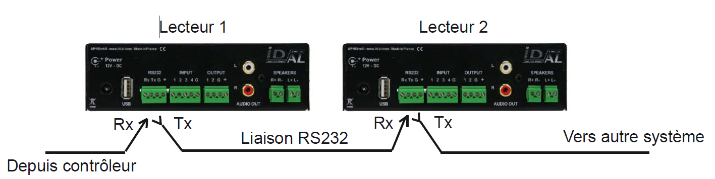
Mode 2: Monitoring
In this mode, the player sends information on the Tx output based on the actions it performs. This mode does not allow chaining players. Monitoring allows an automation system, computer, or security device to know the player's status and perform functional tests. In this mode, the player sends its status with each change.
The transmission protocol is built from a 3-byte frame, similar to the reception protocol.
Byte 1: Status
- b7 = 1: Designates the status byte.
- b6 - b0: Identification of the transmitting player from 001 to 127 (0000001b - 1111111b)
The player address is 001 by default (81h). Modifiable in the config.txt file.
Byte 2 (Command)
Unique value: 00h - 00000000b
Byte 3 (Data)
- 00h - 00000000b: Player ready - The player signals it is ready and available - After power-up and complete startup.
- 01h - 00000001b: Not used
- 02h - 00000010b: Not used
- 03h - 00000011b: Signals start of playback - This code is sent when the player enters playback mode.
- 04h - 00000100b: Signals end of playback - The player signals it has finished playing the current file.
Other values are not used.
Example of a cycle to verify the player's proper operation by playing an audio file:
Preparation: Assume the player number is 001.
Create a folder "001" and copy the audio file (mon fichier.mp3) into it.
Start playback of folder "001" (by activating dry contact 1 or sending an RS-232 command). When the player starts playback, it sends a start-of-playback frame: 81h 00h 03h. At the end of the file's playback, the player sends an end-of-playback frame: 81h 00h 04h.
Mode 3: Extended Monitoring
The extended mode includes the same functions as basic monitoring mode but adds a function for continuously sending its status.
A frame is sent every 250ms describing the player's status among 2 possibilities:
- 01h - 00000001b: Sends a frame indicating the player is not playing and is waiting for a command.
- 02h - 00000010b: Sends a frame indicating the player is playing a file.
This mode is used in the context of security message management. A frame error signals a problem and allows intervention to resolve the issue.
Was this article helpful?
That’s Great!
Thank you for your feedback
Sorry! We couldn't be helpful
Thank you for your feedback
Feedback sent
We appreciate your effort and will try to fix the article